
Clicking on the thumbnail photos will open a much larger copy of that photo.
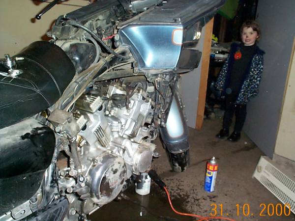
The carbs, exhaust system, rear brake master cylinder, battery, and radiator have been removed. The bolts for the thermostat housing and the starter motor are a bit tight, and I have put WD40 on them. These bolts should remove easily tomorrow. A neighbour's child drops by to see what I am doing.
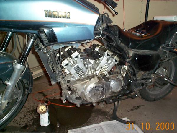
The bodywork has been removed, the YICS chamber, and the air deflector dams. Footpegs and shift lever have been taken off. All of the engine attachment points (except three) have been removed. The small hydraulic jack with wheels will be used to lift and move the engine 2 feet to the waiting "pad".
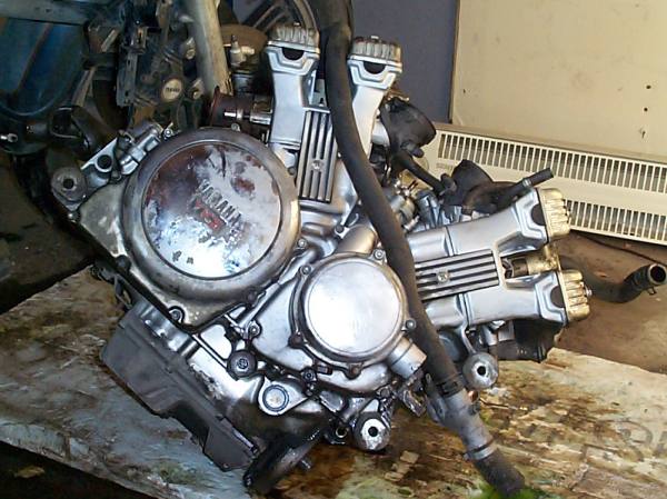
The engine has been out for 10 seconds or so. The engine rests on a piece of blue styrofoam. It is apparent that the engine is also cosmetically not well - just have a look at that chrome cover on the clutch housing!! The rad hoses are still attached. On re-assembly, I found it easier to put the rad hoses on after the engine was in.
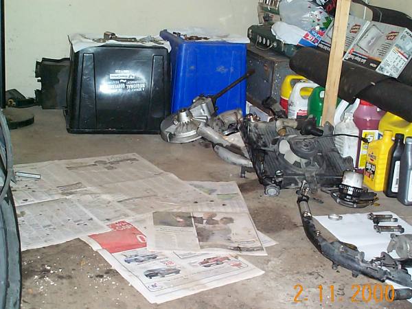
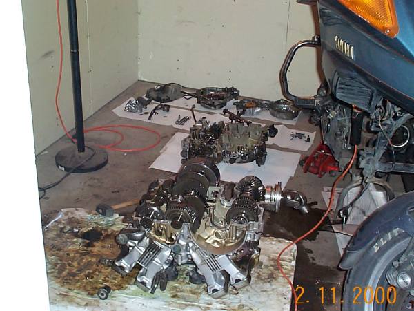
I am working in a fairly small space - the back half of a one car garage. The blue and black boxes hold my tools. The floor has the parts, in order of removal - driveshaft, exhaust components, radiator assemblies, starter motor, and engine mounting hardware.

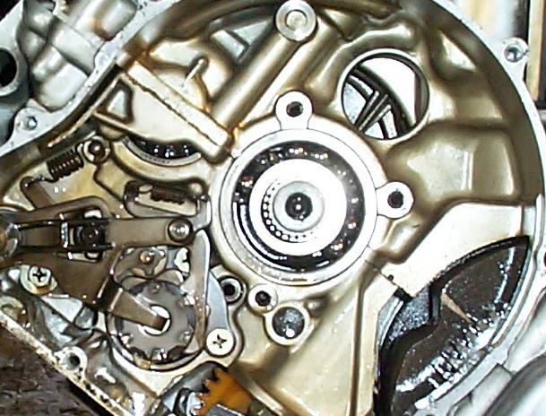
Several photos of the failed bearing. You can see that the balls and race are perfectly fine, but the ball-bearings are all bunched to one side. The bearing cage has failed.

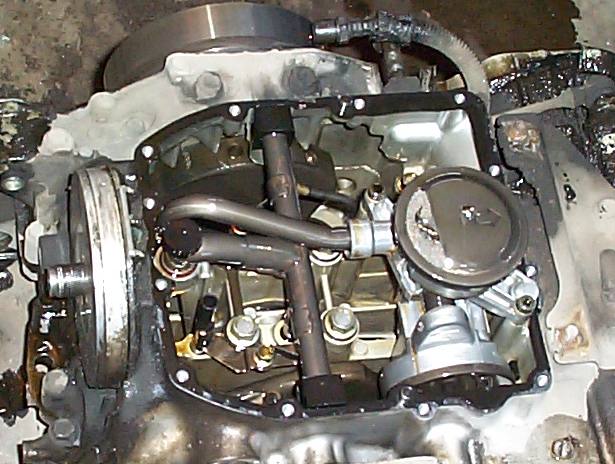
The oil sump has been removed. Two views of the oil pump. You can see small bits of the bearing retainer on the oil pump intake screen. Later, I found other pieces trapped in the baffles on the sump itself.
The various items that attach to the side of the motor are removed (stator, coolant and clutch housings, and the clutch slave cylinder). The oil pump is removed as a single unit, and is not disassembled. The crankcase bolts are loosened in order, and then removed. The crankcase easily pops in half.
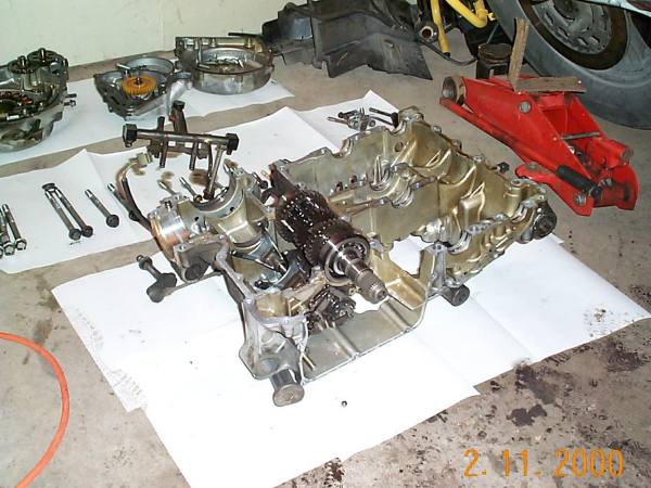
I have placed the shaft with the failed bearing in the top half of the crankcase for this photo. It is only now that I realise that a 2ton press will be needed to remove this bearing. It is a press fit onto the shaft!! This should be an amusing problem to solve. Perhaps I will sleep on it...
I continued with other tasks the next days.