 |
|
|
|
|
|
Not a member? Join Today to see why so many say they are Proud to be a Venturer!
|
|
| Works Performance Shock Rebuild |
|
Author: Jerseyboy Views: 9803 Votes: 4 |
|
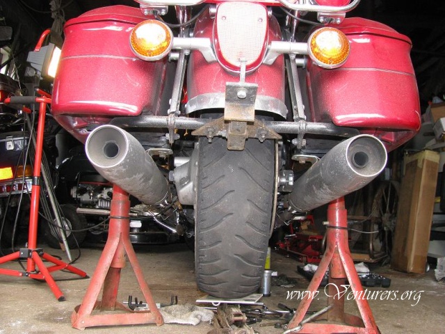
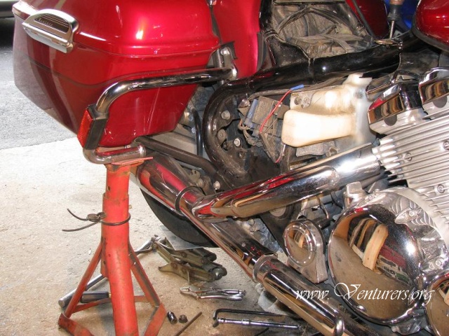
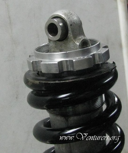
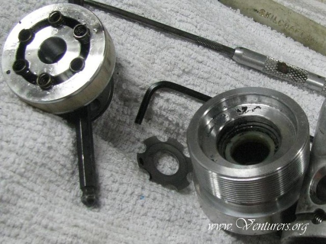
Dis-assembly of Works Performance Shock as Used on Venture Motorcycles 1999-2010. Reference to Pictures. All tools needed are in inches as it is totally made in the USA yet!! Pics of Bike on jacks. #1 and #2.I raise the bike by putting a hydraulic floor jack under the bottom knuckle of the shock and jack it up.I have a Baxley sport chock that holds the bike upright and of course I hold the left handle bar to steady it as it comes up. Then I insert auto jack stands under the bag bars on each side and slide under to remove the shock. I loosen all the bolts first and then I have a small scissor jack to lift the weight of the rear tire off of the shock links and this frees the bolts so I can remove and replace the shock in about 40- 45 minutes at the same time greasing the components with Molydisulfide grease.
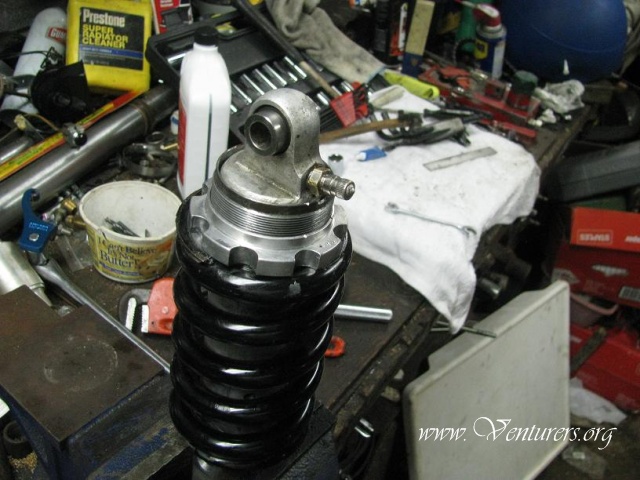
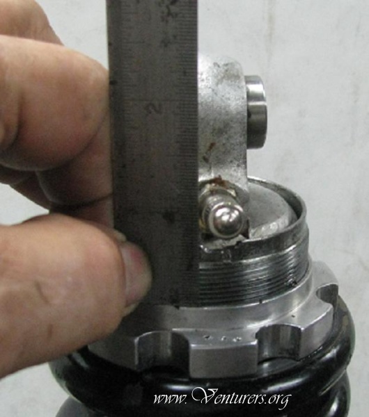
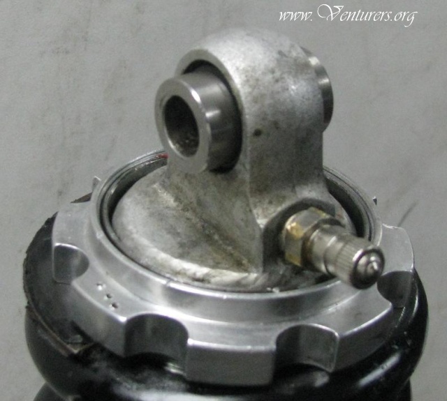
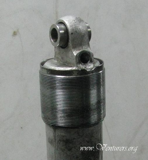
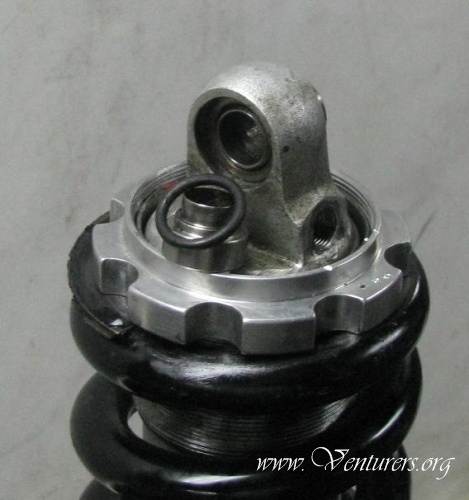
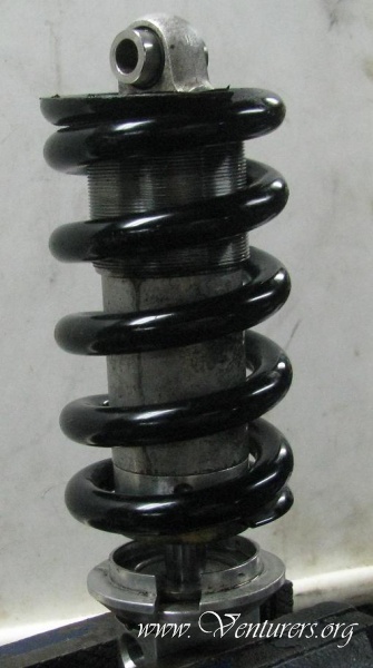
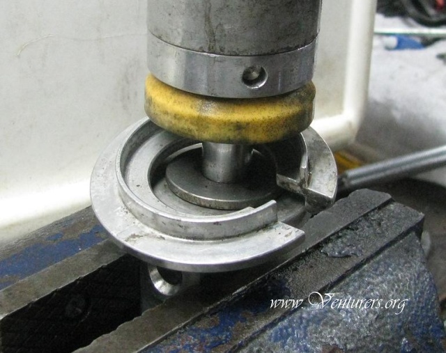
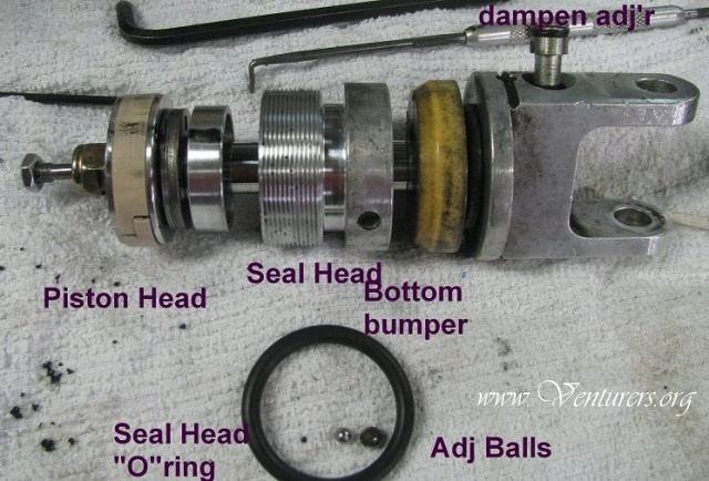
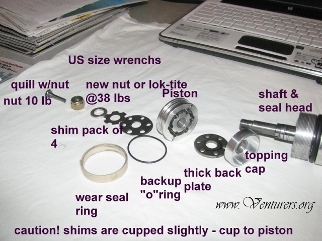
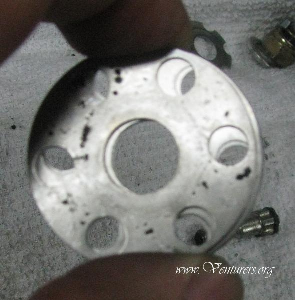
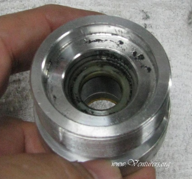
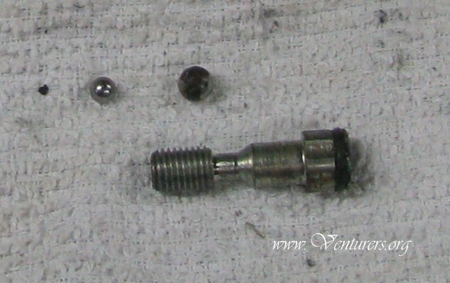
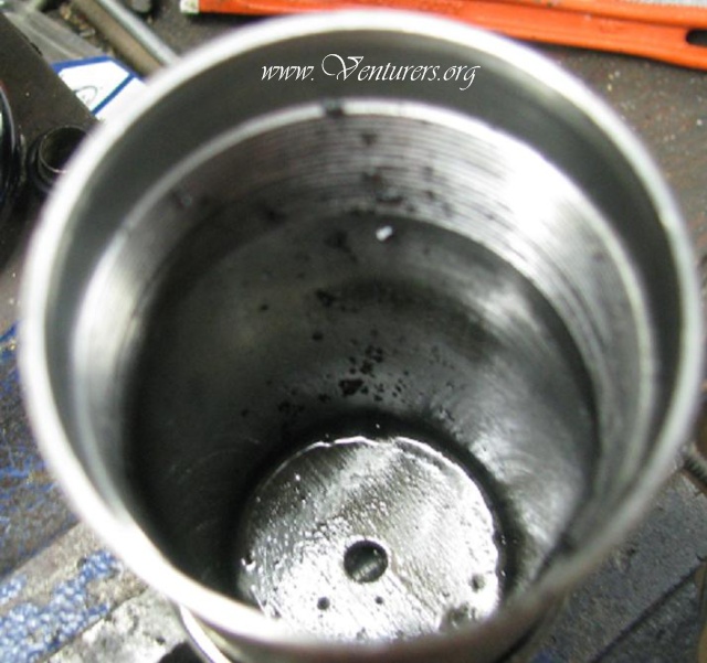
Pic A. Stripping. Each shock is one of a kind for the buyer. If bought from WP they will have orig. info. Pic B. Clean the threads with a brush and WD 40 or equal. Dry. Measure distance of threads from the edge of the adjusting sleeve to the top of the wheel. Mine was 3/8ths of an inch(10mm) I measured at the valve so I could come back to the setting when reassembling. I did make a punch mark on one of the adjuster ears of the wheel (see in pic) to be able to keep track of the turns. Remember turns. Pic C. Bleed air from shock body by covering the valve with a rag and slowly pushing on the valve stem with something other than a body part. The pressure in the shock was 250 pounds at the factory and there is no way you can tell if it has bled off so protect your skin and other parts from being penetrated with high pressure air and oil. It can kill you. Oil and air will come out in a hurry. Pic D. Remove the valve unit from the body with a socket or an open end wrench. If socket will not go over valve due to interference from the threaded sleeve, STOP. There is another way. Alternate method: Back off the adjusting wheel to create clearance between the wheel and the spring. Now using light strikes of a hammer, hit the top edge of the sleeve (Pic J) moving around the sleeve edges and you will see the sleeve start to move down away from the valve. By working the sleeve and the wheel you will be able to get the sleeve low enough to get the socket on and remove the valve. Pic H. The picture shows a cut out in the sleeve on my shock as I had it recharged and to drain the oil the shop had to remove the valve so they used a Dremel to notch the sleeve. So, No harm, No foul. You can do the same thing if you'd rather. If you want to see what's under there remove the spring and just keep tapping on the sleeve and it will go to the bottom and expose the snap ring. It will be dirty under there as it collects road trash. Pic E. This shows the space between the spring and the wheel. Remove the spacer bushings with o-rings for the top mount as they want to keep falling out and it's one less thing to chase around the bench. Pic F. Spring ready to lift off bottom spring seat. Pic G-H. Remove the bottom nest plate and the shock is ready for finishing the oil drain. Position the shock so it will drain by putting a can or something under the hole to catch the oil. Mount the shock upside down, use a spanner wrench to loosen the end cap of the body. You don't have a spanner? Use a drill bit of ¼ inch (6mm) and put the butt of the drill in the hole and use a hammer to give it a few taps to loosen it or use a box wrench to make a bar over the bit and run it out. It is not holding the engine in so it doesn't need a sledge hammer to make it move. The “O” ring is what makes the seal not the tightness. NOTE PIC M. You got the seal head un-threaded now just slowly raise the shaft out of the body and because you have a vent from the valve hole it will rise right out but be aware more oil from the piston will drain. Now take the body out of the vise and lay it aside. Mount the shaft assembly in the vise by the lower fork mount. Pic K. OK. You are looking at the entire piston assembly. Pic L. Full breakdown. This shows the components of the piston assembly. From the left to the right. Loosen the jam nut and the quill may follow the nut right off. When replacing this it should have a bit of Lock-Tite or equal. Before loosening the main nut take a marker pen and make a line from the side of the nut across the washers under it and across to the edge of the piston. Mark the thick lower washer also.(See the mark on the piston in Pic K.) Notice the shims are located so you can see the balls in the holes on the piston. The smaller star washer matches the shim holes. This is for reassembly. Now remove the nut. Note the comment of ”new or Lock Tite”, a factory recommendation. NOTE: The top shims have a slight “cup” on them and they must be returned so the dish, or cup, is facing the piston face. Look for the the marker line. Now take the shaft out of the vise and, holding the assembly together, turn it upside down and put it on the bench vertically. Now let the washer and shins and the piston and the thick washer and the topping cup lower down to the bench top. A few taps may be needed. If not dissembling piston just use small plastic wire ties thru bore to hold together and in place. Pic L1. Bottom of piston and the seal head. Most critical part of work. No mix and match. Note the springs have 2 lengths. Seal head shows interior of head. IMPORTANT: Do not allow the piston and the large thick washer to separate as to let the small OMG springs and the AW Shucks balls get out of their holes in the piston. The springs and the balls are calibrated to the size of the holes in the piston and it affects the rebound action of the shock. If you want to take them out notice a small mark on the face of the piston,(on Mine) on the spring side and make a diagram on paper with 6 spots and the piston mark and set each ball and spring on a spot and the reference dot on the piston will help you re-align and replace the balls. There are no identifiers on the springs so if they go crazy, put your hands behind your head, bend over and ….......scream. The piston has the wide seal ring and under that is the “O”ring that caused my problem. (Pic L). I did the diagram thing so I could clean the debris out of the piston areas and then re-mounted the pieces. Pic L2. The dampening shims from the top of the piston showing more than one, (4 in mine) and they are aligned and re-installed with the dish towards the piston. (I'm guessing here but I suspect the number of shims will relate directly to the amount of resistance needed to cause the shock to react to greater weights. Just my thought. All shims were same thickness so how else to adjust?) Pic L3. Shows the seal head from the inside and the snap ring gap is visible on the far side of the bore. The rest was just general cleaning and re-installing the components in the reverse order. I left the debris in the shock so you can see what it may look like if the interior O ring breaks as mine did. The seal head with the big “O”ring had to be cleaned and as the unit was only about 6 months old I didn't replace the seal but that requires the removal of a snap ring in the bore just above the seal and then use of a drift to drive out the seal and then reinstall the new one and the snap ring. The bumper was in good shape so that was left as was. There is also a metallic bushing guide for the shaft (visible below the seal),that is also replaceable but I didn't need it. RE-ASSEMBLY. Install the seal head on the shaft. Be sure not the scuff or nick the seal. It may behoove you to wrap one run of vinyl electrical tape around the shaft at the step in the shaft. That should preclude any damage to the seal surfaces. Wipe a bit of oil on the tape, seal surfaces and the shaft with your finger to help slide the unit over the shaft and down to the bumper. Remove the tape. Next, slide the topping cup on the shaft with the cup facing the seal head, then put the flat side of the large thick washer on the spring side of the piston. Make sure the holes in the plate are between the springs and install them by putting the shaft down into the washer and piston. Now holding the assembly together, turn the shaft unit upright and mount in the vise again. If you have a new “O” ring install it into the inner groove of the piston then the wide main seal into the out side groove. Do not bow the wide seal to put it on. Simply start one side and gently “walk” the seal around the piston until it drops into the groove. Take the shim stack (mine had 4 shims) and place them on the top of the piston and align the line mark you made with the holes so you can see all 6 balls through the shims. Next the “star” washer and the flat washer. The star to the holes in the shims. A dab of Lok- Tite, and the main nut goes on at 38 pound feet of torque. The final item is the Quill that is screwed in 'til finger tight and then held while the jam nut is dabbed with Lok-Tite and tweaked to 10 foot pounds. Now re-assembly of the shock with the body in the vise upside down. Pic L4. These parts are the adjuster balls and bolt in the bottom fork mount. No service is required under normal conditions. The big dark ball is the detent ball, with a spring in a pit in the lower shock fork, that rides in the grooves at the head of the bolt and the small ball goes inside and by holding the shock upside down it will fall into a hole in the center on the main rod. This contacts a metering rod in the main rod. When the adjusting screw is moved in or out it causes the small ball to ramp up or down on the screw which moves the metering rod up or down thereby changing the speed at which the shock will rebound. It is basically a bypass for oil travel. Pic M. Clean and flush to remove any dirt that may be in the body. I used Brak-kleen as it evaporates and leaves no residue. Highly FLAMABLE. No smoking!!! Wipe out body and blow out valve port if needed. Hand tighten valve into valve port to hold oil fill operation. If you have removed the adjusting sleeve from the body to clean, be sure to re-install it now!! These Shocks are “Ultra” series, emulsion gas shocks and have two overall lengths of seal heads. Type 101 is 2 inches long from outer face to inner end. Type 102 has a shorter seal head which is what mine is, and is 1.440 inches. That converts to 1 and 7/16 long. (1.437 in) Oil can be 10W engine or hydraulic oil, dinosaur or synthetic, but needn't be shock oil. You need a free flowing oil but not automatic trans oil as most is 5W and too thin, and some will eat the o rings. So he said. The shock body is filled to a distance from the oil to the top of the body, in this case, Type 102 without Reservoir, it is 2 - 7/16th inches. I used a machinists depth gauge but you can use a piece of paper towel cut ¼ in wide, that you hang over the edge, 2-7/16 into the body and fill until the paper shows wicking up of the oil at the bottom. You could use a piece of wire bent over the edge also but it is harder to judge for me. Insert the shaft assembly into the body with the seal head against the bumper. Slowly lower the seal head down and start the threads. Wipe the threads and the big “O” ring with fresh oil and tighten the head. Watch the “O” ring as it goes in. You can help by just pushing the sides of the ring to help it find it's way. You can't have any “shaving” of the ring!! Just remember it's not holding the engine in. Don't twist it off. If it took two whacks with the hammer to move it, use 2 whacks to re-seat it. Position the shock upright in the vise and install the spring seat on the base then the spring, and after removing the finger tight valve, the adjusting wheel is reset at the distance you measured on take down. (Note Pic B) I don't recommend lubing the threads or the wheel as it causes the road dirt to gather in the grease causing the threads to freeze up. Clean before dis-assembly. The rule for adjusting weight preload is 2 TURNS = 10%. I determine the pounds of increase of the load, figure what % it is of the original load (mine) and determine the number of turns I need to add to my old setting. Crank them in and test ride. Pre-load for installing a new shock is with the new shock. Now the valve is tightened ( NO PIPE TAPE, IT WILL LEAK tape is a lube not a sealer, pipe dope if anything and only on valve threads) and the air charge installed to whatever you can get from a gas station or home compressor. My home air compressor gives 140 pounds so that's what I have. The use of nitrogen is factory because they make their shocks for competition use and the suspension actions cause monstrous heat buildup. Nitrogen is free of any water vapor, hence no air bubbles to cause the suspension to collapse and maybe cause a crash. It is very stable and the pressure keeps the oil from boiling. High pressure gas is most effective when used in isolated reservoir systems, not our situation. If you wish, take it to a dirt bike shop and they will be able to charge it up to 250 PSI. nitrogen. Well, re-mount the puppy and try it out. Hope this has helped. I've had no problems with mine since my escapade and am not worrying about the next one. These are simple shocks just focus.
Last update: 10:58 AM Friday, July 1, 2011 |
| Related Articles: |
| All material on webpages under the domain venturers.org, is the property of The Venturers, Inc. These materials are protected by copyright and other intellectual property laws. You may not reproduce or retransmit the materials, in whole or in part, in any manner, without the prior written consent of The Venturers, Inc. The free information contained herein is offered in the spirit of helping others and any action or advice taken from these pages is the sole responsibility of the receiver. |