|
Introduction: Sadly, as we’ve all come to learn, the RSV (a great bike – IMHO) does leave a bit to be desired when it comes to rider “arm” comfort. The relatively flat bars used on the second generation and their lack of adjustability (a significant loss from the 1st generation model (and my GoldWings, as well)) results in wrist and neck pain for many riders’.
To remedy this condition we have a couple of options:
- The use of “Risers:
- GenMar // Part #Y122 = $89.95 + shipping & handling
- Baron’s // Part #: BA-7430-00 = $69.95 + Shipping & handling
(Current prices listed – You actual price may vary)
- The complete replacement of the handlebars, associated cables, and hydraulic brake & clutch lines
Having gone the riser route with some success and satisfaction, and having noted (with envy) the many positive comments from fellow Venturer’s regarding their Flanders conversion, I decided to make the change prior to the Spearfish II ride-in this summer. Having made the change and ridden the ride (5,200 miles total) – the answer is in… I’m very, very glad I did it!
What follows is a step-by-step tutorial for anyone considering this change out…
Note: Not everything shown or discussed below will be required to complete the bar change out process, but since the opportunity to accomplish these other tasks was presented, they were done concurrently (each optional procedure will be identified as such).
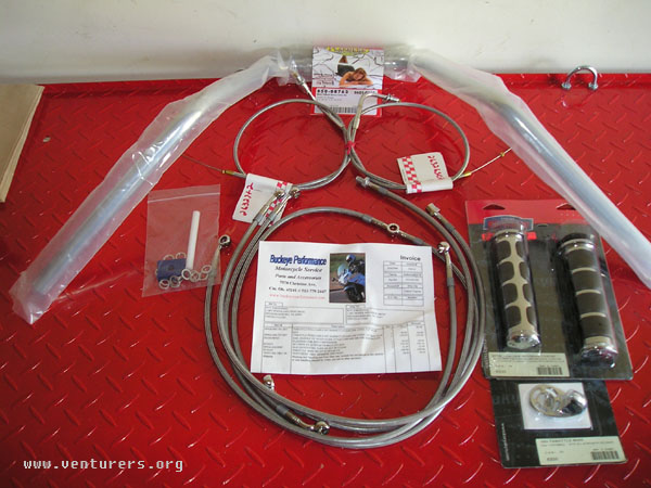
Project Conversion Parts (required):
Braided Stainless Steel 5 Hydraulic Line set = Part #: BP426-426-999C
Flanders pull back handle bars = Part #: FL650-08763
Barnett SS Cable Sets
Throttle Push Cable = Part #: BP426-450-327 SST
Throttle Pull Cable = Part #: BP426-450-327 SST
Optional Parts:
Kuryakyn ISO Grips = Part #: KU6235
Kuryakyn ISO Throttle Boss = Part #: KU6250
Suggested/Recommended Source: Buckeye Performance
Contact Rick @ Buckeye Performance for the complete conversion package that he has set up for RSV owners. This one stop shopping source will provide the bars, custom throttle cables, and extended hydraulic clutch and brake lines, in your choice of SS or OEM black. He is also a source for Kuryakyn throttle conversion parts as well.
www.buckeyeperformance.com
513-779-2447 // 513-779-2615 fax
info@buckeyeperformance.com
Tools, Equipment & Supplies needed:
Torque wrench
Allen key set (ball end recommended)
Metric socket & ratchet set
Metric open end wrench set
Phillips head screw driver(s)
Brake bleeder device (I used a Mity-Mite)
DOT-4 Brake fluid
Estimated Time: Approximately 5 hours (including optional procedures)
The process:
Note: One of the optional procedures performed at this time was a cooling system flush & fluid change, as well as an oil & filter change; therefore it was necessary to warm the bike up before beginning my bar conversion.
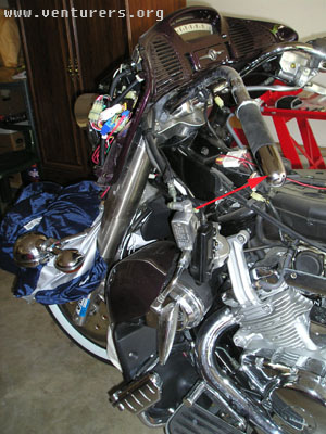
To start off - Remove the seat, fuel tank, and split the fairing. Note: I removed the radiator shroud and also the right side panel covering the overflow reservoir to do some optional fluid changes/service items.
|
Removing the gas tank. |
|
|
|
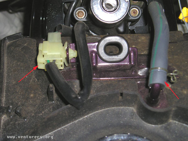
First - Remove 2 screws (#5 hex head) from the ignition switch cover and remove the bolt (12mm (11ft/lbs)) at the rear of the tank.
Next remove the electrical connector at left front of the tank and “split” the connection. Then remove the vent hose on the right side of the tank.
Remember: Turn fuel petcock off (if you don’t normally do so when parking the bike), then disconnect the fuel line (Note: A small amount of fuel will leak from line (you may want to plug the line with a small screw/bolt)) – I just drained the line into a small can and dried the line with a shop towel before removing the tank.
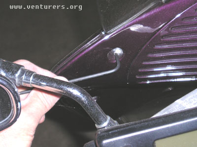
Next step is to remove the rubber covers on the mounting lugs at the front right & left side of the fuel tank.
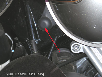 
Remove the 2 screws that are now exposed (#4 hex head (62in/lbs)).
You may now lift the tank off and set it out of harms way for later reuse…
Note: It is recommended that you begin this process with a nearly empty fuel tank as gasoline weighs approximately 6 lbs per gallon and the tank is no light weight either!
|
|
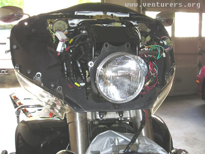
Splitting the fairing – Required in order to remove cable ties and route replacement lines |
|
|
|
|
This process has been described many times – Although often thought of as intimidating and complex it is, in reality, quite simple. Just take your time and work carefully as the parts are plastic and mounting tabs have been known to break and screw bosses will strip if too much torque is used.
- Remove the top two screws at the upper outer edges of the fairing using a #3 hex key
- Lift the chrome windshield trim up & out (carefully) the mounting tabs are fragile
- Remove the remaining six screws at the outer edges of the fairing using a #3 hex key – Note: Upper two screws are threaded full length.
- If you have passing lights installed on your bike you will have to lower them out of the way, unless you have installed the spacer assembly made by our own “Poco Red” – If you don’t have one installed, this would be a perfect time to add this handy item which will allow you to split your fairing without performing the next step.
- After removing the plastic cover from the light bar remove the screws using a #6 hex key and lower the bar to the front fender (be sure to pad the fender well to prevent damage).
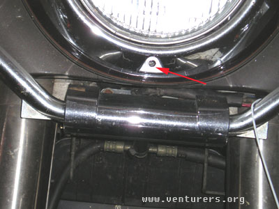
- Remove the screw from the bottom center of the headlight and lift the fairing off the bike and set it aside until reassembly.
Note: This Next Step Is Optional
- Replace headlight bulb – I elected to install a Silver Star #9003ST halogen bulb while the fairing was split.
a. Note: If you have large hands you might consider removing the top two bolts from the headlight assembly (#5 hex key) as it makes the job much easier (I did it without removing them)
b. Pull the plug from the rear of the lamp socket
c. Move the spring clip out of the way
d. Turn the bulb to the right (1/4 turn) and remove old bulb
e. Install new bulb – Carefully – Don’t touch the glass as the oil on your skin will shorten the bulbs life
f. Reassemble, install housing screws (if removed) and retighten
|
Stripping the bars – Preparing for the Replacement |
- Remove all plastic plugs from clutch & brake assemblies and attachment points on old bars in order to remove these parts – You should have a minimum of 8 plugs (4 large from the center of the bars and 4 small for the clutch & brake housings)
- Remove clutch housing assembly (use short Phillips head screw driver) and radio control pod
- Remove Bar weights in order to remove throttle assembly for reuse
- Pull plastic end caps
- Remove mounting bolt using #8 hex key
11. Remove front brake assembly
12. Remove old bars – Leave throttle assembly in place until bars have been removed, then slide the throttle off the end of the bar
|
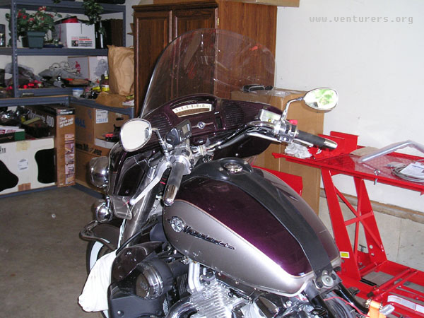
This is the mid-point of the Bar Replacement Project:
Total time was approximately 1 hour and 40 minutes |
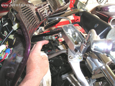
Install Flanders® bars by attaching them to the center mounting point on the steering head assembly – Do not torque bolts at this time
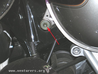
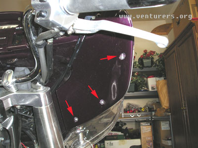
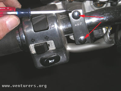
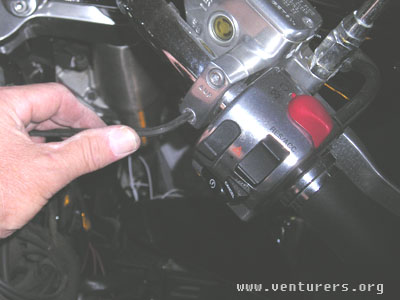
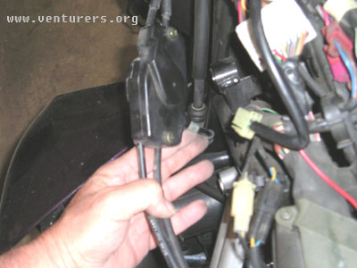
- Remove left side plastic neck cover to gain access to the throttle cable junction box
- Remove Phillips head screw from top of the plate assembly – Note: The bottom “screw” is actually a push pin and does not unscrew
- Pull plate cover from frame mounting boss
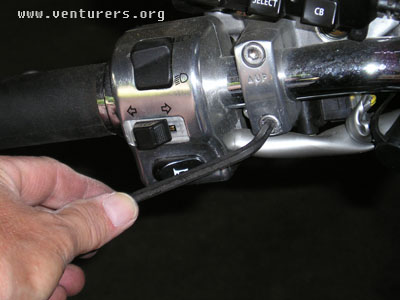
- Remove cable wire guide rubber strap in front of throttle box (Save for reuse)
- Open cable clip to rear of throttle box and pull box away from frame in order to get at screws on the back of the box
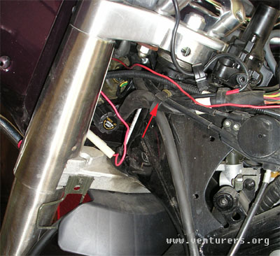 
- Install new throttle cables
- Using old cables as a guide insert the new cables along the same path taken by the old cables – Note: You may find that feeding the cables with your left hand and guiding with the right to get them around the steering head (while standing at the right side of the bike) might make this job easy to do
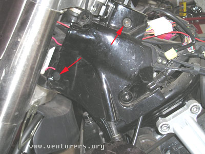
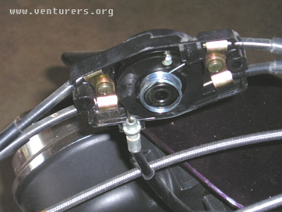
- Once the new cables are in place – remove the old cables by opening the throttle box (2 Phillips head screws) – This is what you’ll see – Don’t worry, it’s easier then it looks
- Remove the spring
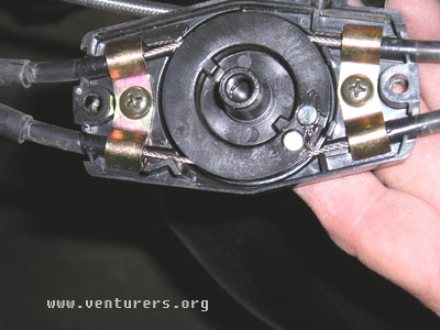
- Remove the front cable bracket by removing the Phillips head screw
- Lift the black plastic “wheel” to remove throttle cables
- Remove one cable at a time and replace with corresponding extended length SS cables – When completed, reassemble the junction box cable bracket and spring unit
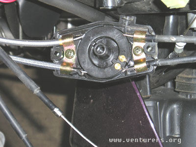
Note: Photo does not show spring reinstalled – be sure to include it before closing the junction box
- Reinstall the box – clips – and cable band removed earlier
- Replace plastic neck plate
TOTAL TIME TO DISASSEMBLE – REPLACE CABLES - REASSEMBLE THE JUNCTION BOX WAS ABOUT TEN MINUTES (Took longer to write & photograph the process then to do it)
- Remove old throttle cables – feed them out to the right side of the bike
|
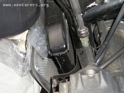
The next step is to replace the front brake lines |
- First drain the existing brake fluid from the front brake master cylinder
- Either remove the old lines from the brake calipers and insert into collection cans then open the top to the fluid reservoir and slowly squeeze the handle – or –
- With a brake fluid vacuum pump (I used a Mity Mite) perform the following steps
i. Connect the unit to the brake bleeder at the caliper and apply a vacuum
ii. Open the reservoir top
iii. Open the bleeder and allow the fluid to be drawn into the collection bottle – repeat until the line is empty
iv. Move to the other side and repeat to drain that brake line as well
REMEMBER – Brake fluid will ruin your paint – so work carefully
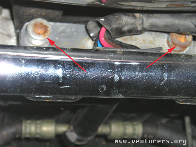
- After draining the system – Cover the rear of your fender and remove the bolt at the junction block where the u-shaped line connects to the fluid line coming from the handle bar reservoir
Note: These will be 12mm bolts at all junctions
- Remove the 10mm bolt which connects the brake line to the routing loom which holds the DOT reflector to the fork tube – Repeat on other side
- Replace line with new SS line – Start at center and work out towards end – Try to take advantage of the inherent curve in the line and fit accordingly – Mine didn’t quite lie flat and it isn’t easy to reshape to conform to the bikes’ lines
|
Next replace the upper front brake line |
-
Remove lower bolt behind the light bar (12mm) 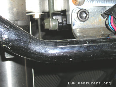
-
Remove line from the reservoir and feed the old line out through the steering head/fairing assembly – Note the path of the old line as you will have to install the new one via the same route
|
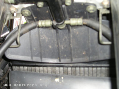
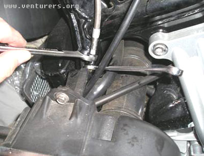
Next replace the hydraulic clutch line |
- Drain the fluid reservoir by breaking the clutch line at the junction in front of the engine (Use 10mm & 17mm open end wrench) – You can lift the line sufficiently to get access to the connection
Note: Collect the fluid – Do not allow to come in contact with paint
- Remove the bolt connecting the line to the reservoir (12mm)
- Feed the old line down and out – Be sure to make note of the path used as you will replace the old line with the new SS line via the same route
- Connect the upper and lower junctions
|
Next reassemble the handle bars – Reinstall throttle; brake; clutch; and radio units as required |
| 
 2006 Tech Contest Winner