 |
|
|
|
|
|
Not a member? Join Today to see why so many say they are Proud to be a Venturer!
|
|
| Fitting OEM CB To Non-US RSV |
|
Author: Aussie-Dave Views: 11132 Votes: 1 |
|
FITTING OEM CB TO NON-US MODEL RSV I had an Australian model 99 RSV which does not come standard with CB. This, I understand, is the same as the European models. I acquired a CB, passenger push-to-talk (PTT) button, wire loom and handlebar control unit on e-bay and then fitted this to the bike. Here is a description of the process and most importantly, the wiring directions for a successful mount. I no longer have the bike but I have used photos provided by Oliver in Europe, Equipment list:
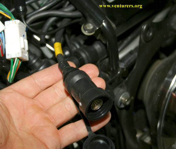
I mounted the CB in the trunk – simply slid it into the little ‘net’ type pouch that is there – the CB was standing on its side (edge) in the trunk. I had the CD mounted vertically in the trunk as well and this helped keep the CB in place (as well as sliding the owners manual alongside the CB so all was snug). The cables ran through the large hole that is already located in the front right of the trunk – just enlarge the grommet. The signal splitter is the size of a small packet of cigarettes so I put that and the cables neatly under the grey foam to the front right side of the trunk. The stereo / CB head unit is located under the front fairing. All the components have DIN plugs (not sure what this stands for) that plug directly into the unit. These are colour coded – as shown in the picture below, the CB plug is coded YELLOW:
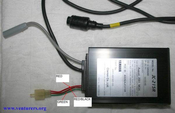
There are a number of wires coming out of the CB and these are used as follows:
Two options:
· Antenna · Splitter · SWR tuner · Patch cable - splitter to CB – this is a co-ax screw type at one end and a Motorola one at the other – only about 4 inches long. · Patch cable – this cable is a co-ax type with screw socket on both ends to run from base of antenna directly into the splitter – mine was 18 inches long. You could also consider a 90 degree elbow connection on the base of the antenna – this allows the cable to run straight under the trunk and is a cleaner look. These elbows are available at radio shack – be sure not to over tighten these when you screw them into the antenna base as they will break easily – just a light snug to tighten. · New standard antenna cable – Motorola plugs both ends run from head unit under fairing to splitter in trunk – maybe 6 feet needed. 2. New antenna solely for the CB: Having one antenna for the radio and one for the CB is a good set up and I would go down this path if I was to do it again. The antenna would simply need to be plugged into the CB using the 18 inch long patch cable as described above. I purchased the rear PTT assembly with my other items. I removed the rear speaker assembly and accessed the two screws that hold the switch in. This switch had the volume and PTT button and there were a few wires:
The PTT and speaker wires terminated in a black plug with six terminals. This is located under the pillion seat and is secured to the frame with a black plastic tab.
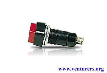
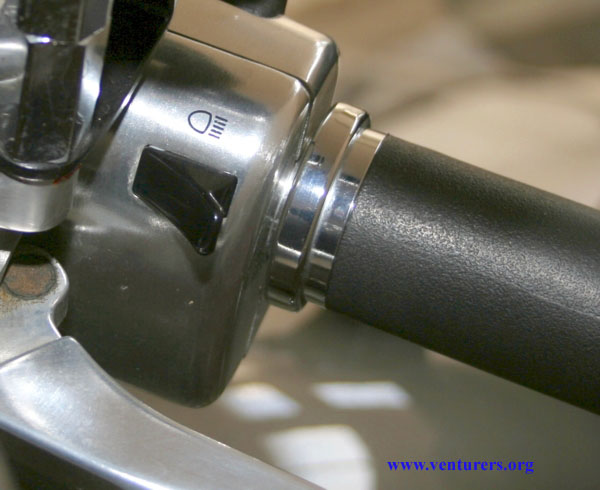
I made my own push to talk button and velcroed it under the left indicator switch housing within easy reach of my thumb. The switch is a momentary on/off switch from radio shack and looks like this:
I ran an earth (ground) wire off one terminal (soldered to it) and the other wire goes to the pink/blue wire in the main loom as described above. A quick connect is all I needed for the pink/blue wire. Slide some shrink tubing onto your two wires to the switch before you connect ensuring the tube goes over the terminals on the switch – this can then be heated and shrinks over the end to make it waterproof. The length of wire can be covered in the shrink tubing and fed along the wires already on the handlebar into the front fairing. I put a piece of Velcro under the indicator control (the horizontal surface) and then wrapped a sticky velcroe strip around the switch – around the black part below the red button. This could then be secured to the indicator housing.
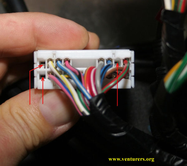
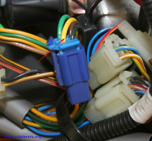
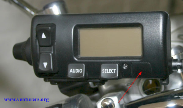
‘Oliver’ has tested and determined that the yellow wire under the front fairing in the blue connector is the live wire for the headlight flash switch. Therefore, if this wire was cut and the switch end connected to the pink/blue in the loom then when the button is pushed, it will activate the PTT instead of flashing the headlight….I will probably do this next time instead of putting on separate switch. At this stage, the CB is in the trunk connected to the antenna (or splitter), the auxiliary power (activated by the ignition switch), to permanent fused power, earth (ground) and PTT under front fairing. The other issue now is to work out if the non-US model handlebar control unit is set up for the CB but without the CB select button…as shown below:
If you now have the correct handlebar control unit, and it is connected to the head unit, you can now turn the CB on and test the PTT button. When CB is on and you push the PTT button, a code of ‘TX’ appears on the handlebar control unit (transmit). You now need to tune the antenna with the SWR tuner. The tuner must be connected between the antenna and the CB…it has been described under http://bludolphintravel.com/gmg/marshallmod.htm
Last update: 07:44 PM Thursday, March 9, 2006 |
| All material on webpages under the domain venturers.org, is the property of The Venturers, Inc. These materials are protected by copyright and other intellectual property laws. You may not reproduce or retransmit the materials, in whole or in part, in any manner, without the prior written consent of The Venturers, Inc. The free information contained herein is offered in the spirit of helping others and any action or advice taken from these pages is the sole responsibility of the receiver. |