 |
|
|
|
|
|
Not a member? Join Today to see why so many say they are Proud to be a Venturer!
|
|
| Correcting E1 & E4 errors on the air controller. |
|
Author: Auton Views: 21201 Votes: 20 |
|
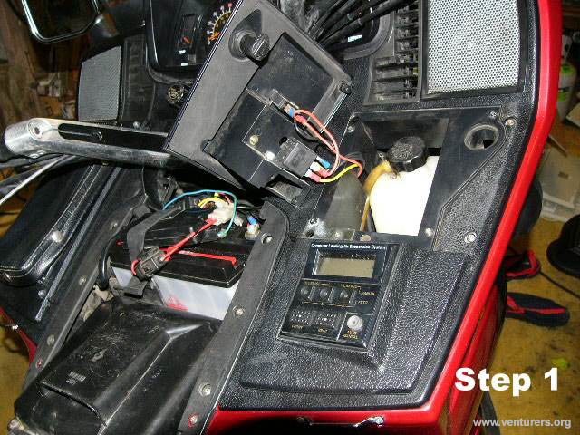
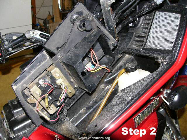
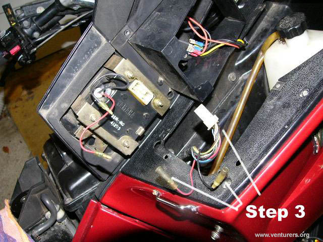
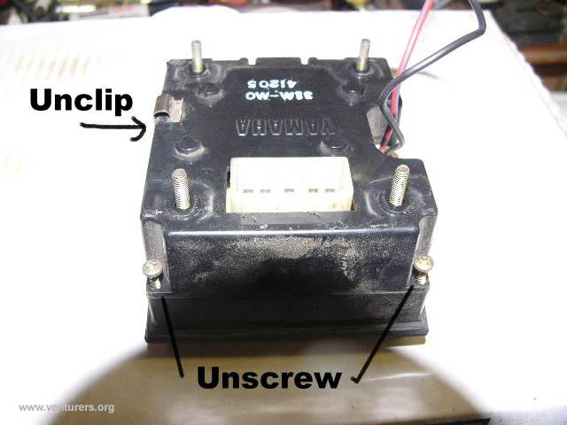
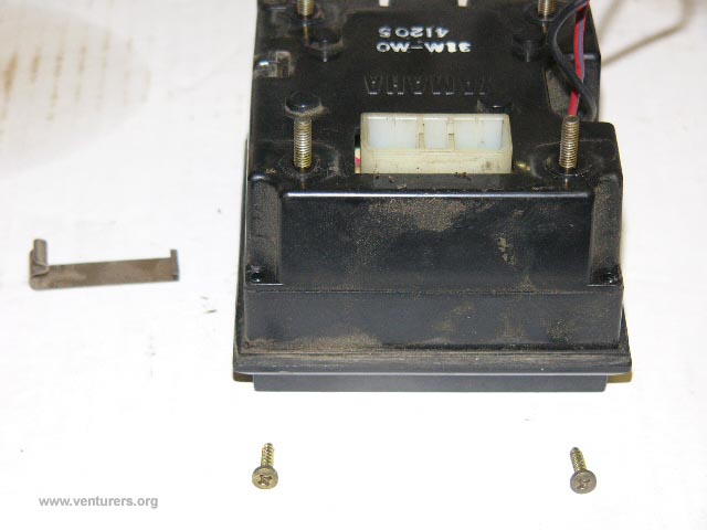
Air Controller Error E1 & E4 Repair Procedure This repair was carried out on a 1985 Venture Royale. The first indication of a fault is the air controller displaying an E1 or E4 error. There may be other errors depending on which connections are not working. Remove the false petrol tank cover Disconnect battery by removing connectors off one terminal. Pull leads away from terminal wrap in rag. Place second rag over battery to prevent any chance of short circuit. Remove the access panel. Remove the 4 screws that hold down the air controller cover, slide cover towards bars to release base. CHECK THE WHITE CONNECTOR IS FULLY PLUGGED IN and there is no stress on the wiring with cover in place. If fault is still present then continue as below. Disconnect battery once again and cover with rags to prevent short circuit. Disconnect wires Black and Red, these will require holding the cable each side of the connector and giving it a good tug to break joint. Push in release tab on the main white connector (midway on long side of connector) and pull out plug from the controller. Undo 4 small nuts at rear of controller and remove brackets, support the controller on the display side to avoid dropping it on the ground. Carefully slide the controller out from the panel, watch the rubber seal is coming away clean to avoid breaking the seal. Place controller "display down" on clean newspaper on your bench, remove small clip on side of controller, removal is easy with a pair of long nose plyers through the raised clip. Remove the two small screws.
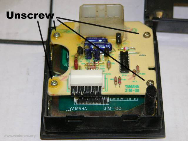
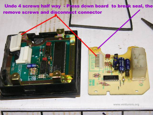
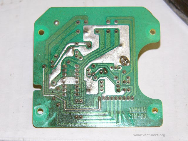
Lift cover off back of controller to expose circuit board, undo 4 screws holding down circuit board half way out. Push board down close to each of the sealed screws to break the seal. When done fully remove the 4 screws. Disconnect small white connector that connects the two boards together. Use long nose plyers to force connector apart a fraction at each end, repeating until it becomes free. You will have to hold the top circuit board while you disconnect this connector. Try not to stress the connecting wires. Turn board over to show circuit tracks and solder joints. Note the dust on my board, brush off any dust with a horse hair brush (paintbrush), DO NOT USE NYLON OR PLASTIC BRUSH as this may cause static electricity that will destroy the internals of the integrated circuit (IC) on this board.
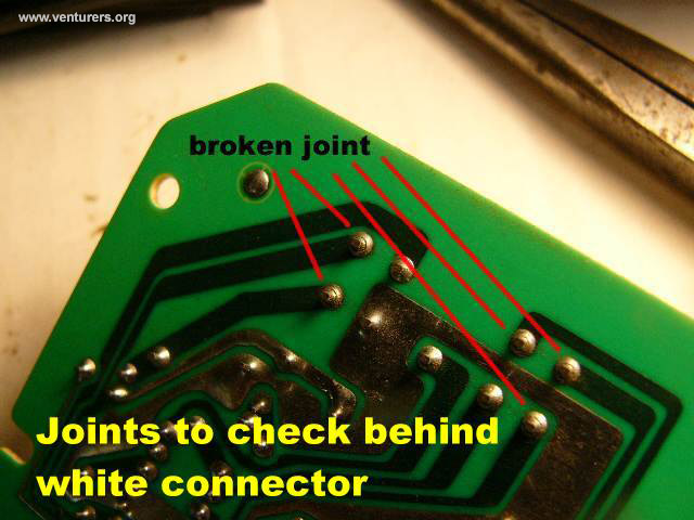
Using a small iron with resin cored solder apply a little new solder to each joint and confirm the joint is shiny. If dull then iron may be to hot. If you are not keen on doing this soldering then take the board to your local electronics shop to have the work done. When finished clean up extra flux with needle between all the tracks and connections. Check for any solder bridge between pins or tracks and remove. Use a magnifying glass to check your (Their) work. Brush board with horsehair brush (paintbrush to remove any small dots of solder.) Note the joints highlighted in the following picture. My controller had a number of broken joints.
Reverse procedure to assemble. Take to bike and plug in large white connector. Switch to acc on key. If all is working as it should be with no errors. Install coolant cover panel. Reconnect battery and confirm air controller operation is correct with no errors. Install dummy petrol tank cover. Reset your clock. Enjoy your new ride. Any problems or questions contact neville TAC NOTE: One of thing first things to check is the plug connections for any corrosion, bent pins, opened ports or push out pins before you dive into the controller.
Last update: 10:15 AM Monday, December 19, 2005 |
| All material on webpages under the domain venturers.org, is the property of The Venturers, Inc. These materials are protected by copyright and other intellectual property laws. You may not reproduce or retransmit the materials, in whole or in part, in any manner, without the prior written consent of The Venturers, Inc. The free information contained herein is offered in the spirit of helping others and any action or advice taken from these pages is the sole responsibility of the receiver. |