 |
|
|
|
|
|
Not a member? Join Today to see why so many say they are Proud to be a Venturer!
|
|
| 1984 Yamaha Venture - 2nd Gear Repair |
|
Author: Wayne Corley Views: 95224 Votes: 90 |
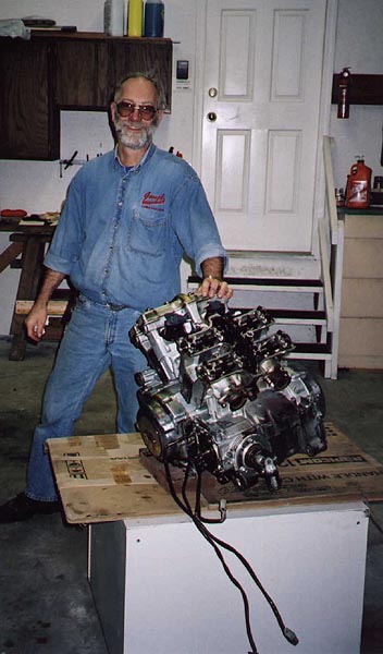
Part 1 - Engine Removal
I found the Venturers web site in February of 1999 and promptly joined and it became a goldmine of information as I learned about my trusty steed. One of the common problems found on the 83 to 85 Ventures was a failing second gear. I kept hearing of this problem but continued to see no evidence of the problem on my bike. I kept my fingers crossed that the problem wouldn't crop up as it seemed a huge problem to tackle. I had heard of other Venture owners either riding the bike without any second gear for long periods, or giving up and parting bikes out rather than repairing them. One Venturer, Scott MacMartin, had done his second gear repair several years ago and he had posted a parts list on his personal website. He also had a more recent parts list contributed by another member. The list seemed formidable. I kept hoping mine wouldn't develop the problem. Finally the inevitable. My second gear started to skip under full throttle in September 2000. I nursed it along, keeping a light throttle hand through to the end of riding season. Coincidentally, Scott updated his website in September with a pictorial description of a repair to his main clutch bearing. While not aimed directly at the second gear repair, he showed a number of great tips that would help in the repair. I had a shop manual and after studying it for hours and repeatedly checking Scott's site I decided to tackle the problem over the coming winter. I figured I might save money on parts if I got to it before the gear failed completely. Also, I didn't think I could get much selling the bike without 2nd gear, nor did I want to keep riding it without 2nd. Hell, 2nd is my favorite gear. Like a lot other first generation Venture owners, I had come to really like this bike, it's a real runner. At any rate, I kept a log during the teardown and took a number of photos, with the idea that they might be of assistance in reassembly in case I ran into any problems. After getting most of the work done, I decided to try putting this into a web page with the idea of helping other Venture owners gain the confidence to tackle this job. I am not a professional mechanic therefore, anything I write here is simply my own experience with this repair. My only intention is to pass on some information and knowledge to other Venture owners who may wish to attempt this repair. Think of it as preserving the breed. Don't take this project on lightly, but it is within the grasp of a good home mechanic.
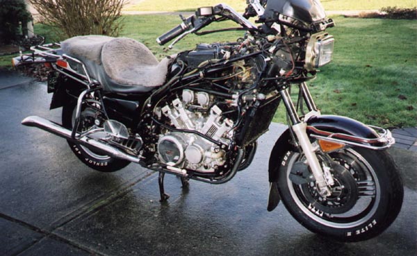
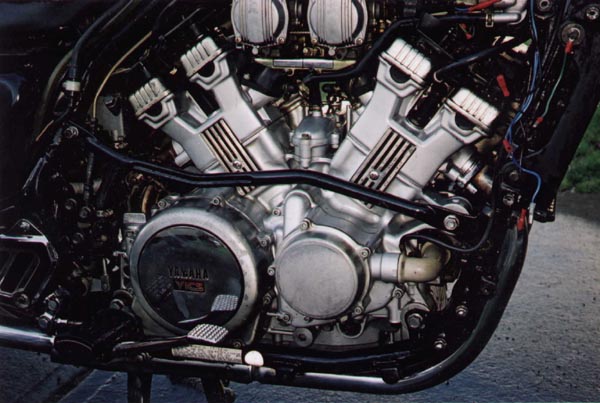
I'm basically a lazy mechanic. I hate trying to fight my way around things. I'd rather take the time to properly gain access as it makes it easier in the long rub. I started by removing all the luggage, fairing, auxilliary lights, horns, etc to get proper access. A simple technique I've learned is to clean parts as I take them off and put fasteners for each component in a zip-lock bag. The bag is labled and kept with the component ready for reassembly. It's a lot easier to sort through a half-dozen parts at a time rather than a few hundred at a time. Especially if your project takes a number of weeks. I then washed the motor and frame to get rid of as much grease and grime as possible prior to dismantling. (I use Simple Green and a brush as degreaser.) I then warmed the bike up thoroughly to dry things out. With the bike still warm, I drained the oil and removed the oil filter. The battery was then removed and the carb float bowls drained. The engine coolant was then drained. Don't forget to drain the cylinder heads. There are plugs behind the chrome inserts on the side of each cylinder. The air cleaner box and carbs were next off. I found that the drain hose on the air cleaner was loose on mine. The hose drains off residue from the crankcase ventilation. With it disconnected it had sprayed all over my carbs. A few hours of cleaning was required. The crankcase ventilation hose was hardened and cracked during removal. The first item for the parts list. Clean rags were stuffed into the intake manifolds, to remain there for the duration of the repair process. Next to go were the bypass hose, YICS chambers, and Air Baffle plates.
The radiator and coolant hoses were removed next along with the footpeg assemblies and the middle gear case cover. I then disconnected the AC Generator leads, neutral switch lead, and pick up coil lead. The clutch slave cylinder was loosened and the hose left connected. I wanted to avoid having to bleed the clutch fluid again as I had done that recently. Not a great plan. I found during engine removal that it would have been easier to disconnect the hose and remove the engine with the slave cylinder in place. The mufflers were then removed. The rear wheel was removed and the drive shaft taken out. I then remounted the rear drive and wheel as I wanted to be able to move the bike around when the engine was out. The front exhaust headers were removed as well as the baffle chamber under the engine. The rear exhaust header was loosened. It would come out when the engine did. I unbolted the rear brake master cylinder and reservoir as instructed in the manual. Again, I was trying to avoid a brake bleeding. However, the clearance was such that I ended up taking them right off to get the engine out anyway. Might as well have done so from the start and saved some sweat.
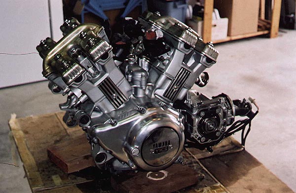
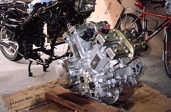
The right lower side rail was then removed and with a wheeled floor jack supporting the engine and the help of a couple of friends we managed to wrestle the engine out. A couple of points. The shift mechanism had to be disconnected to enable the clutch slave cylinder to come free. It would have been easier to disconnect the hydralic line and remove the slave cylinder with the engine. Also we tried to turn the engine out of the frame. We ended up removing the rear brake master cylinder and reservoir as well as the rear cylinder valve cover to get enough clearance to lift the rear mounting bolts clear of their frame slots. Once clear of the frame we carefully lifted the engine onto a wheeled cabinet. With the engine safely out of the bike, I was ready to move on to phase two of the project!
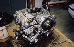
Part 2 - Dismantling the Engine
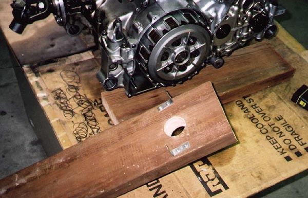
With the engine successfully removed from the frame, I was ready to dig in to see what was wrong. The next few hours were spent thoroughly cleaning the engine exterior, top and bottom. It was time well spent as it made disassembly a much more pleasant job. The added benefit is that it's a lot easier to keep dirt and grime out of the engine if it is clean to begin with. The thermostat housing was then removed followed by the starter motor. Both of these parts could have been removed prior to removing the engine. This would have given a lot more clearance. I will not put them back on until the engine is back in the frame. The next step was to remove the left crankcase cover. The starter gear train is then loose and it comes out easily. The right crankcase cover (clutch) was next. As I had changed out the clutch plates and springs the year before, this was quite straight forward. The plates were stacked and wrapped. The clutch pushrods were then removed. Be careful to catch the ball bearing that resides between the two pushrods. A tip from Scott's website helped in getting the clutch lock nut off. You need a special tool to hold the clutch boss while loosening (or re-torquing) the lock nut. Scott used a 2x6 with a couple of brackets to hold the boss and a hole to allow the socket to go through. It works great! You'll need a 30mm socket for the job however.
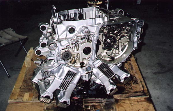
I then inverted the engine and thoroughly cleaned the bottom side. The oil pan came off next. The oil pump assembly comes out with three bolts. I originally didn't plan to dismantle it but after a word with my friendly local bike shop I pulled it apart to inspect for scoring on the pump impellor surfaces. Clean as a whistle and quite easy to put back together. The main oil gallery was removed as an assembly. Be sure to make sure all the oil seals come out with the gallery. Note: One of the gallery bolts is also one of the lower crankcase bolts (#20) and should be installed and torqued in the proper sequence upon reassembly.
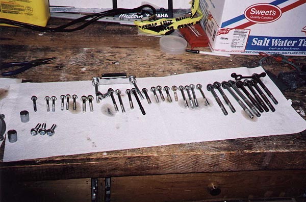
The crankcase bolts are numbered. There are 36 of them and it is extremely important that they be reinstalled and torqued in the proper sequence. Taking them out in reverse sequence allows you to lay them out in order saving considerable confusion and time when reassembling. Start by turning the engine right side up and removing starting with #36 which is also the ground strap bolt. A nice touch on the Venture is that all 36 are actually marked right on the crankcase assembly. (Bolts # 31, 30, 28 & 27 will loosen but you cannot take them out with the cylinder heads still in place. Just let them hang loose, as they will not get lost.) (Note, in my shop manual the illustration on page 3-22 shows the crankcase tightening sequence. Unfortunately, the diagram captions are reversed with the lower crankcase labeled the upper crankcase and vice- versa.) The clutch bearing retainer needs to be removed prior to separating the crankcase. This retainer has large phillips head screws which will require an impact driver to loosen. I hadn't used one of these since owning a 1970 Kawasaki 90 many moons ago. On that bike, every screw was a phillips head and you couldn't do anything without an impact driver. I had to go an buy one. The middle gear bearing retainers also have to be removed prior to separating the cases. This retainer uses Torx 40 fasteners. I bought a Torx 40 socket for the job. (If I keep tackling these jobs, I'll eventually end up owning every tool known to man. Is that a bad thing?) The three bolts holding the collapsible collar holding the driven pinion gear will also have to be removed prior to separating the cases. Be careful not to bend the thin shims behind this collar. Since I will not be changing any parts on the pinion gears, I plan to re-use the shims and believe that the gear lash will not be disturbed. I did not disassemble the U-joint assembly. With all fasteners off it was surprisingly easy to separate the crankcase assembly. A couple of taps with a rubber mallet and off it came. A couple of hours were spent cleaning the residue from the crankcase mating surfaces. The next step was diagnosing the problem.
Part 3 - Diagnosis & Repair of Transmission
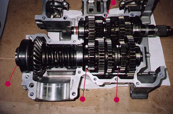
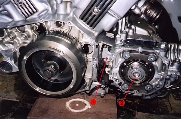
It also became very apparant as to what the problem was. Even though there was very little wear on the second gear dogs or gears, when in second gear, the gear dogs were only overlapping by a millimeter or so. With the large torque in 2nd gear, the gear assembly would put a tremendous amount of sideways force on the shift fork allowing the gear (#1) to move to the left and jump a cog or two. When the shift fork was inspected it did turn out to be bent.
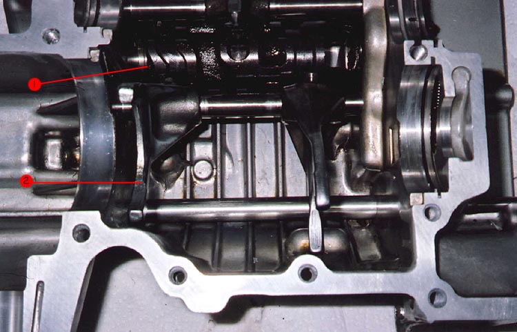
The picture at right shows the shift cam and shift forks. The #1 shift fork (2 in picture) was slightly bent and required replacement. The shift fork shaft can also bend from the stresses of skipping. To check it, remove it and roll it across a mirror or plate glass. Any bend should show up clearly. Mine was OK as was the shift cam, probably because the problem had just started. The shift cam (#1 in picture) needs to be carefully inspected for wear in the groove that the #1 shift fork rides in.
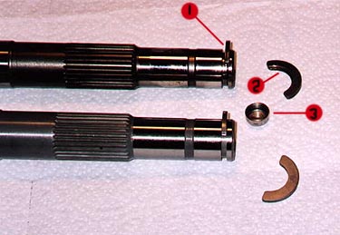
The homemade press at left was suggested by Scott MacMartin on his web page and it worked beautifully. It is constructed from 2x6 and large screws. The floor jack compresses the spring and forces the center of the shaft up into the hole in the middle section (arrow) and allows you to remove the thrust washers. The next picture clearly illustrates the basic problem. The wear on the old thrust washer (#2) is evident as is the wear on the slot on the transmission shaft. The combination produces the gap (#1) in the slot. This gap allows the whole shaft to shift inboard reducing the overlap of the 2nd gear dogs. Once it gets to a critical point, the gear is forced sideways by the torque allowing it to skip. This sideways force will eventually cause the shift fork to bend. It also would cause the fork to wear the groove in the shift cam. The bent fork and wear on the shift cam would further reduce the overlap on the gear dogs until there is no second gear at all.
Note the plug (#3) in the photo. When I ordered the new Drive Axle, the plug didn't come with it. It could be easily overlooked when reassembling. Without the plug, there would be no oil pressure inside the Drive Axle, hence very little if any oil getting to the gear surfaces. Be sure to order this as a separate part as the old one will not fit properly in the new shaft. I was able to continue with reassembly while waiting for this plug as it is easily popped in after the engine crankcase is put back together as it is on the outb oard side of the shaft. With all the replacement parts on hand, I reassembled the Drive Axle, installed the new shift fork and once again laid the transmissions shafts in the lower crankcase assembly mated the shift forks. I manually ran the transmission through the gears several times until I was satisfied that everything was in the right place. The transmission shafts were then transferred to the upper crankcase assembly in preparation for reassembly.
Part 4 - Engine / Transmission Reassembly
A few points to watch out for before mating the upper and lower crankcases together. First, be sure to replace the clutch push rod oil seal and O-ring prior to reassembly. It is possible to replace the seal once the bike is back together but impossible to replace the O-ring as the collar it fits on is keyed to the crankcase. I oiled up all the main bearing surfaces and poured some oil into as many of the galleries as I could access with the thought that this would aid lubrication upon startup. Apply Yamabond (or Threebond) to all mating surfaces. It is very important to apply in the areas surrounding the oil galleries to ensure good oil pressure. Also, keep the Yamabond at least three mm away from any of the main bearings to prevent contamination. Don't forget to position the Drive shaft pinion gear at this point. I didn't worry about checking the pinion gear lash as I took it out as an assembly and dropped it right back in. Dropping the lower crankcase into place is quite easy. Touch it down at the front end and as you drop the rear end, guide the shift forks into place on the transmission gears with a screwdriver. Once again, shift through the gears a couple of times manually before tightening anything down. Install and torque the crankcase bolts in the proper sequence. One of the bolts holding in the main oil gallery is also one of the crankcase bolts so I mounted it at the same time and torqued the bolt in the proper sequence. I installed new O-rings on the main oil gallery. The engine was now turned upright and the spacers on the shaft drive yoke were slipped into place and the upper crankcase bolts were installed and torqued. The drive yoke bolts were then positioned and torqued. I then had to re-invert the engine to install the oil pump assembly (new O-rings again) and the oil pan with a new gasket.
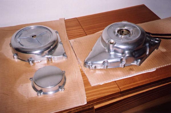
While all the internal repairs were taking place, I also took some time for some cosmetic external clean-up. The crankcase and waterpump covers were showing the ravages of UV rays and the factory coating was a mess. Liberal applications of Minwax Paint & Varnish Remover took care of the old coating. A thorough polishing with NEVR-DULL and Mother's Metal polish restored the shine. A fresh coating of clear coat high temp laquer provides the protection. Prior to installing the clutch boss, be sure to re-install the oil pump drive gear. Another tip of the hat to Scott MacMartin. His Clutch Removal tool works like a hot-damn and is easy to build. The piece of 2x6 with a couple of shelf brackets provides more than enough grip to break the main clutch boss nut free and also to re-torque it upon re-assembly. The hole provides room for the socket to grip the nut, while the "tool" holds the boss tightly. I just love great ideas, particulary when they are cheap to implement. The remainder of the clutch plates, and springs were added and the bolts torqued.
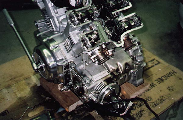
The starter gear train was installed along with the AC Generator Cover. (A new gasket, of course, was also installed. With the engine on the bench, this is the ideal time to check and adjust the valve clearance. A whole lot easier than when it is in the bike. No bashed knuckles here. It turns out there were a couple that were tightening up a bit too much so with some shim swapping, everything is back to spec. New valve cover gaskets went on at this time but the rubber bolt plugs looked in good shape so I stayed with the old ones. The right crankcase cover goes on next (new gasket) and we're just about ready to re-mount the engine.
Part 5 - Re-Installing the Engine
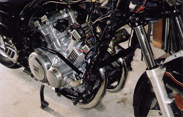
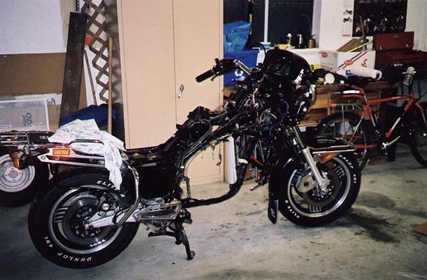
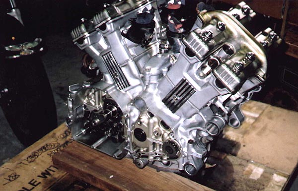
I'm doing a few things differently from when I pulled the motor out. In an effort to gain as much clearance as possible and simplify the task I've left a few things off and put others on. In the left view of the motor, the clutch slave cylinder is mounted to the engine and the shift shaft linkage is connected. This will be two less things to fiddle with when remounting the engine. The downside, and it's minor, is that I will have to reconnect and bleed the clutch line. In the right view, notice that the water pump, thermostat assembly and starter motor are not in place. This provides some much needed clearance on the front end. Further, the drive shaft is still not in place so all I have to worry about there is getting the yoke into the swing arm and I don't have to worry about mating the splines at this point. The rear brake master cylinder is also not in place. I had to remove it to get the engine out and since I plan to upgrade the brake lines anyway, bleeding the brakes will have to be done regardless. The lower right frame rail will also come off to provide room. I had it re-mounted to the to keep the parts together. One last point prior the task is to have the rear exhaust header handy. It has to go in with the motor. You can't put it in after the fact.
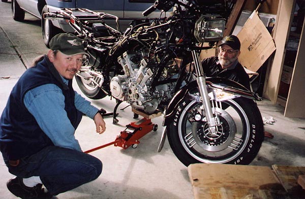
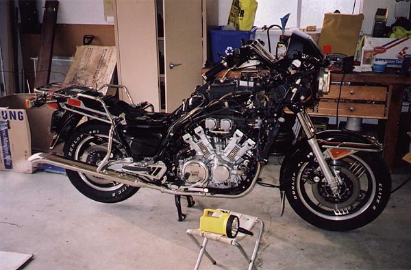
It required a bit of jockeying back and forth but in about 15 minutes, it slipped into place. Three of the mounting bolts were put in and we're there. The lower picture at right shows the engine in place with the water pump, thermostat assembly, starter motor and lower frame rails all bolted into place.
Other steps at this point are:
I let her warm up thoroughly and then hooked up the mercury stacks. The carb synch was virtually spot on. A week later I had a new set of stainless steel brake lines installed and fresh set of spark plugs. Insurance on and time to take her for a short test ride. I still had no fairing on the bike, therefore, no signal lights and no mirrors so I kept it short. (It was also darned cold.) Shifting is very smooth through the gears, good power with no clutch slip and best of all, no skipping in second gear. Yahooooooo!!!! Still lots to do to get her ready for a summer of riding but a big job complete.
Part 6 - Parts ListingThe following are lists of parts and materials that I found necessary for this project. Your experience may vary depending on how badly worn your transmission is. For example I didn't replace the shift cam, which may be necessary if you have virtually no second gear. The lists are broken into four parts and all prices are in CANADIAN dollars and include Provincial (BC) and Federal sales taxes. Your prices will vary of course, depending on your locale, dealer and tax systems. The prices are only published here as a guide. The first list contains the parts that I found were specific to the 2nd gear repair. As my 84VR had only just started skipping, this should be considered a minimum. I have included gaskets and seals that can only be accessed with the crankcase split. I believe that they should be considered essential changes as part of this repair.
The second list contains materials that were necessary for the job. Some could be considered regular maintenance, but needed to be changed as part of the process. I did not include materials I already had on hand such as solvents, and polishing compounds.
This third list contains some special tools I needed to purchase for the job. I have a fairly substantial work shop, but I still needed a few special items.
The last table lists the other parts that were purchased for general winter maintenance. This includes a brake overhaul, cooling system overhaul and general tune-up items. This list sort of grew with the project and kind of got out of hand. However, it all goes towards maintaining a sound reliable bike.
Last update: 11:02 PM Wednesday, May 12, 2010 |
| All material on webpages under the domain venturers.org, is the property of The Venturers, Inc. These materials are protected by copyright and other intellectual property laws. You may not reproduce or retransmit the materials, in whole or in part, in any manner, without the prior written consent of The Venturers, Inc. The free information contained herein is offered in the spirit of helping others and any action or advice taken from these pages is the sole responsibility of the receiver. |