 |
|
|
|
|
|
Not a member? Join Today to see why so many say they are Proud to be a Venturer!
|
|
| Charging System Testing |
|
Author: TN_Tim Views: 49545 Votes: 31 |
|
The RSV charging system uses a permanent magnet type AC Magneto (ACM) alternator. The stator and rotor of the alternator are located inside the left engine cover. The rotor is attached to the crankshaft and contains permanent magnets. The stator coil is mounted stationary to the engine cover and is surrounded by the rotor magnets. When the engine is running, the spinning magnets around the stator coil create an AC voltage within the windings of the stator. The AC voltage produced by the alternator is converted to DC voltage by the Regulator/Rectifier (RR) which is mounted on the frame of the bike near the oil filter. The RR sends a regulated 14 volts DC to the bike’s electrical system and shunts excess voltage to ground. Charging System Specifications: Output: 14 Volts / 300 Watts / @ 5000 rpm *The AC Voltage spec is not listed in the Yamaha factory service manual. Observed output is from known good systems. See test procedures below. Test Equipment Needed:
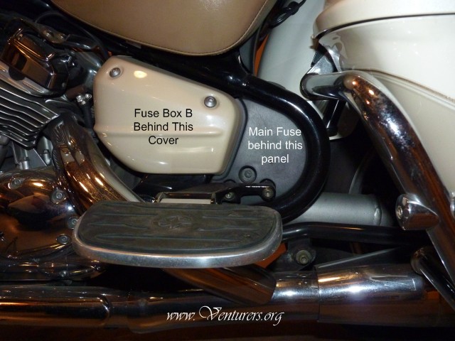
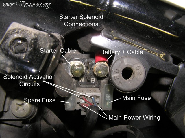
*Not all meters operate exactly alike. You should be familiar with your meter and understand how to operate it correctly to avoid misinterpreting the readings. Testing Charging System Output Using your volt meter, read static battery voltage with all systems turned off. A fully charged battery should read 12.6 volts. If battery voltage is low, it should be charged before testing the charging system. A weak or defective battery may cause false test results. Have the battery tested or replaced if it will not achieve a full charge from a battery charger. With a fully charged battery, start engine, turn off all electrical accessories. Read battery charging voltage as engine speed is increased to 5000 rpm. Charging voltage should be 13.5 ~ 14.5 volts. If the voltage is around 14 volts, the charging system is OK at this time. If you have been experiencing intermittent charging system problems, double check all connections in the system. If charging voltage is below 13.5 volts, possible causes are poor connections, defective wiring, defective stator, and/or defective RR. Higher than 14.5 volts indicates possible defective RR and/or poor connection. If the charging voltage is out of specs, check all connections in the system. This includes battery cables, RR connector, stator connector, solenoid connectors, and main fuse connection. All power to and from the battery must pass through the solenoid / main fuse connections, so don't forget to check these when diagnosing electrical problems. The solenoid is located behind the left side cover and the black plastic cover behind the left passenger floorboard. Testing The Stator Engine and ignition switch turned off. The stator can be tested at a couple of different places. For now, we will be testing at the RR connector. Access the RR connector by removing the two 10mm RR mounting bolts and lowering the RR. (Removal of the RF lower fairing makes it easier to access the RR bolts.) Disconnect the connector and inspect the terminal pins for looseness, corrosion, or damage, and repair as needed. Regulator/Rectifier location.
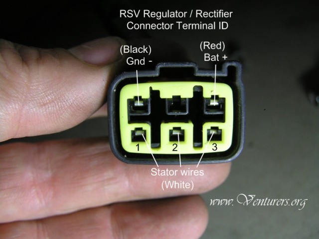
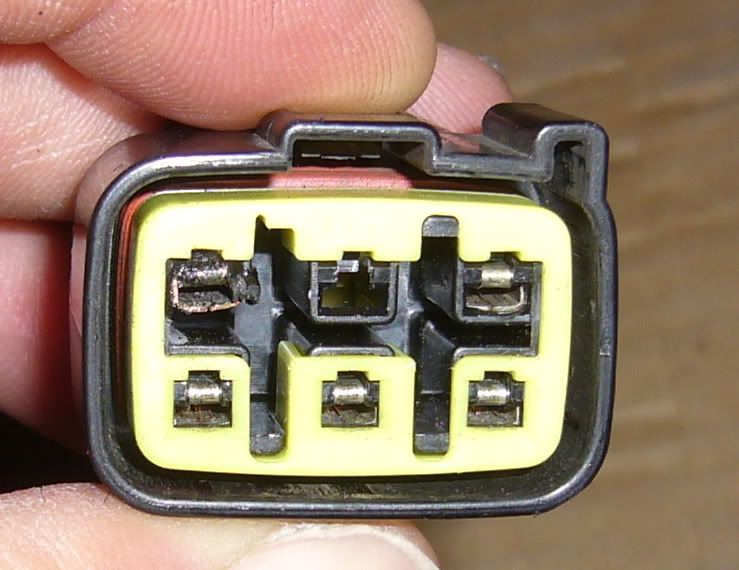
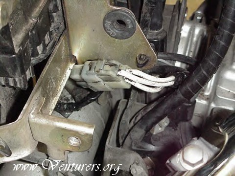
Check for battery voltage between the connector terminals marked Bat+ and Gnd- to insure those circuits are good. Be sure to inspect the condition of the connector terminals. The photo below is an example of the result of a poor connection at the R/R and the resulting overheating and melting of the plastic connector. The poor connection caused a "no charging" condition and a dead battery. Note the burned / melted terminal at the top left:
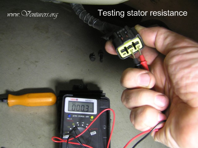
Check the stator coil resistance by measuring at the three stator terminals of the connector shown above. Set the meter to the lowest ohms scale and measure between pins 1~2, then pins 1~3, and finally between pins 2~3. All readings should be approximately .3 ohms. Note that some meters may not read accurately at this low setting and we are testing a little farther down the wiring harness, so don’t be too concerned just yet if you don’t get exactly .3 ohms. Next, with meter set to a higher ohms scale (>100 ohms), connect one meter lead to a good engine ground and use the other lead to test each stator terminal for a short to ground. All should read open (OL) or very high resistance.
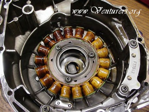
Check the AC voltage output of the stator. Set your meter to read AC (NOT DC) voltage on the 100+ volt scale. Start the engine and read each pair of terminals in the same order as you did above, 1~2, 1~3, 2~3. At normal idle speed, voltage should be around 20~25 volts AC on each pair. Rev engine to 4000 RPM and read voltage on each pair again. Voltage @ 4000 RPM should be around 100~110 volts AC. All pairs should read equal voltages. If one pair reads significantly less than the others, or if all read significantly lower voltage than specified, the stator may be defective or there may be a connection problem at the stator connector where it connects to the main wiring harness. If you get questionable readings, you’ll need to retest at the stator connector located behind the side/center covers below the rider’s seat. This connector is very difficult to get to which is why we are testing at the RR connector first. However, it should be noted there have been cases of the stator connector below the riders seat suffering from poor connections and overheating/melting of the connector. If you find a problem with this connector, it can be cut out and the wires soldered directly to each other to eliminate future problems with the connector. The stator connector. This photo shows the stator mounted inside the engine cover.
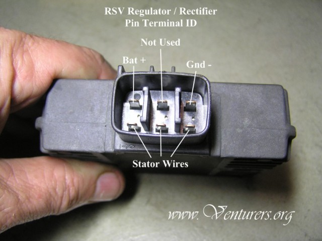
Testing Regulator/Rectifier (RR) Note the positions of the RR terminal pins below.
Set the meter to "Diode Test" as indicated by this symbol. 1. Attach red lead to the Bat+ pin, touch black lead to each stator pin on the RR. Each pin should read "OL" (open circuit) on the meter. 2. Attach Black Lead to Bat+ pin, touch red lead to each stator pin. Each pin should read about .5 volt. 3. Attach red lead to Gnd- pin, touch black lead to each stator pin. Each pin should read about .5 volt. 4. Attach black lead to Gnd- pin, touch red lead to each stator pin. Each pin should read OL on the meter. If any of these readings are not as specified, the regulator/rectifier is defective.
Last update: 02:28 PM Sunday, August 15, 2010 |
| All material on webpages under the domain venturers.org, is the property of The Venturers, Inc. These materials are protected by copyright and other intellectual property laws. You may not reproduce or retransmit the materials, in whole or in part, in any manner, without the prior written consent of The Venturers, Inc. The free information contained herein is offered in the spirit of helping others and any action or advice taken from these pages is the sole responsibility of the receiver. |