|
Continued from page 1:
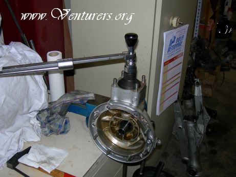
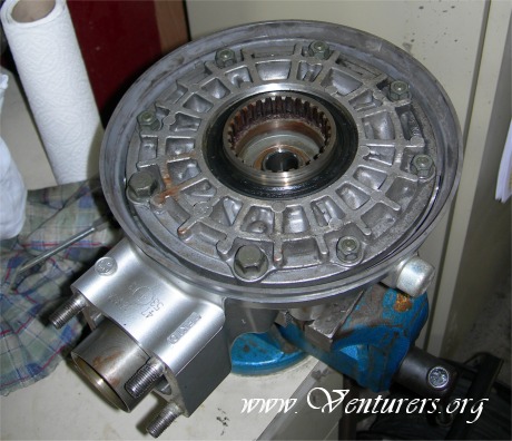
After a well greasing of the seals, we put the bearing retainer in place. Tighten with help of Yamaha special socket in invert clock wise at the tightening torque of 80 ft/lb.
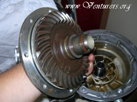
We put the gear coupling in place.
After have been placed the washer, we put locking agent on the nut and the pinion screw (the blue liquid we can see there). With the help of the Yamaha special gear coupling holder and a 22 mm socket on a tightening torque wrench, we tighten the nut (torque of 80 ft/lb, clockwise).
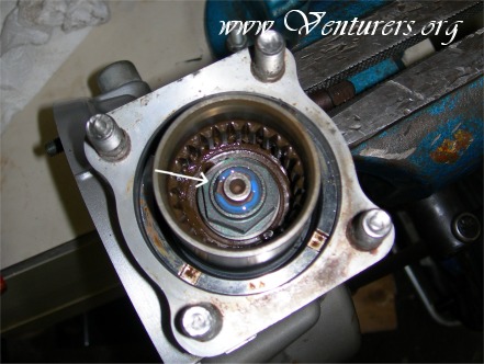
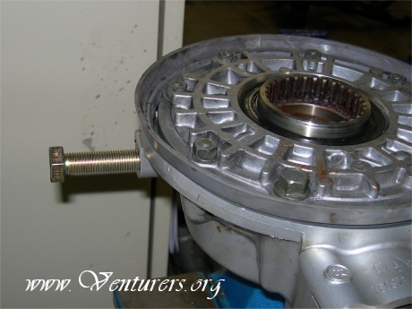
After tightening, we stake the nut with a punch on the pinion axle's spline (at arrow).
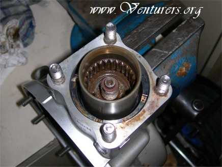
Ready for the following operations…
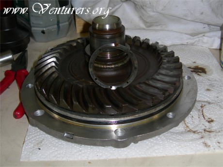
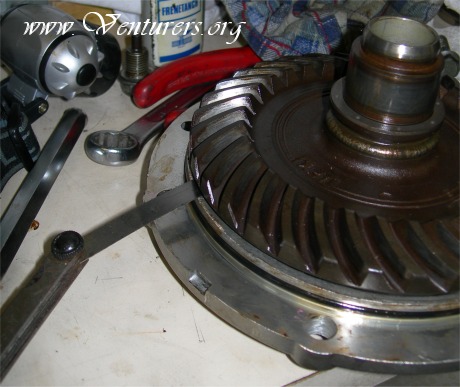
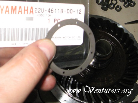
The gear case cover, with the ring gear and it's thrust washer in the centre.
We close the gear housing : don't forget the ring gear's thrust washers, and be careful for the gear case cover's O ring. Tightening torques: 29 ft/lb for the 2 bolts, 17 ft/lb for the 6 nuts (don't forget the blocking washers). Tightening in crisscross pattern.
At this moment, I can ear all the people say:" well repaired, ready to go !". Forget that ! Due to the repairing, and the miles covered with a faulty assembly, it's necessary to adjust the gear lash. This gear lash can be measured only if the assembly is complete, with the correct tightening torques everywhere, to have reliable measurements (all the components of the assembly are well and precisely machined)
The first stage is to block the ring gear. We remove the drain plug, and put in its place the special bolt (self made from an industrial metric bolt 14x1.5x100). I had especially reduce the final diameter of this bolt, to have contact with the ring gear (for the new RSV, not necessary for the 1st gen bikes). Tighten it gently by hand.
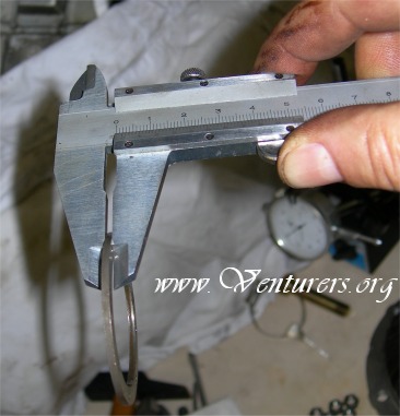
In a second stage, we attach the gear lash measurement tool, on the gear coupling. This tool is self made ( the measure must be take at 2.36 inches from the pinion's axle).
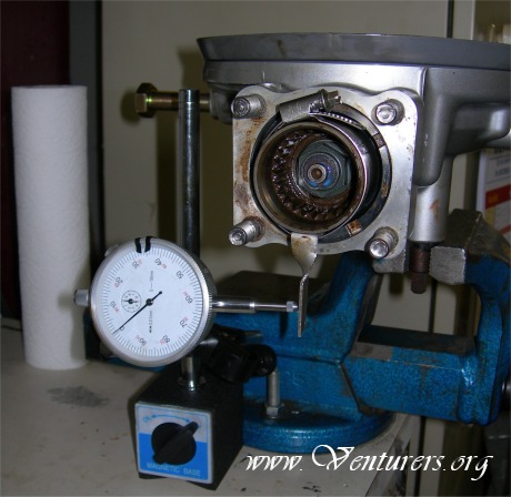
In a third stage, we prepare the dial gauge and its stand. On this view all is in place for the measurement. The gear coupling is pushed gently until blocking, on the right side. We adjust the dial gauge, to obtain "0" marking on its meter.
We turn gently the gear coupling to the left, until blocking. During this operation, the little arrow indicate "1" ( = 1.00 mm =0.04 inch) and the big one " 16 " ( = 0.16 mm = 0.006 inch). Our first measurement is "1.16"mm ( = 0.0.46 inch)
Yamaha San says that we must have 0.25 to 0.50mm (=0.01 inch to 0.02 inch), who means about 0.1 to 0.2 mm gears clearance (= 0.004 inch to 0.0078 inch). Note on the pad the measurement, and repeat 4 time the same operation, in turning the measurement tool, 90° each time.
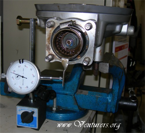
We open the assembly again to make adjustments to the backlash.
The important tool now is the note pad! After making note of the gear lash (1.16mm = 0.046inch) we measure the ring gear's thrust washer (here was 1.8mm = 0.07inch).
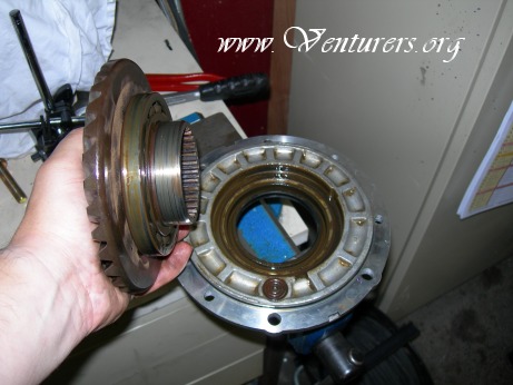
Removal of the ring gear (by pushing it gently with a soft hammer). There's shim(s) on the back of the ring gear's bearing (like that we can increase or decrease the space between the ring gear and the pinion). In our case, we know that the ring gear is too far from the pinion. We must logically increase the shim(s) thickness. We can see the big ring gear's bearing, in its back.
We measure the original shim's thickness and we note it on the pad. In our case, we have 0.5mm (= 0.02 inch). 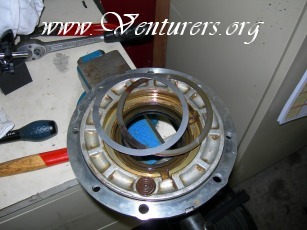
After many, many tries, we arrive finally to the good thickness : 0.8 mm (= 0.031 inch) composed by 2 shims (1 x 0.35 mm plus 1 x 0.45 mm). Pay attention that, for each try of thickness ( 0.55, 0.60, 0.65 mm, etc ), we must close correctly the assembly, with the correct tightening torque's specifications, and repeat the complete gear lash measurement. We note on the pad all the thickness shims and all the measurements, only to don't forget anything. Count one day for this operation !
The final shims are in place in their housing.
We re-close the gear case cover. After a last try, and a last measurement proceeding (final control), we re-open the assembly to measure the ring gear's thrust washer and the stopper bolt clearance.
We measure the stopper bolt clearance with a feeler gauge. This clearance must be from 0.3 to 0.6 mm (= 0.012 to 0.023 inch). We have now 0.9mm (= 0.035 inch), we must correct it, by ring gear removal…
The stopper bolt is out. We see the shims inside its housing.
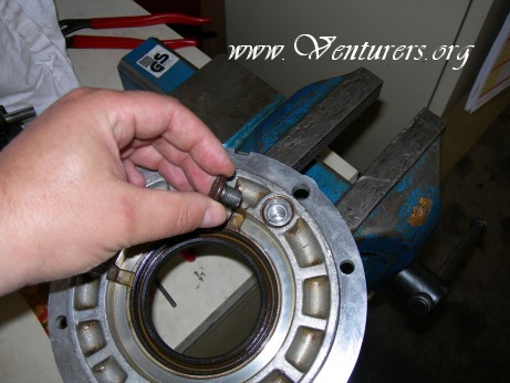
The stopper bolt : unscrew it with the 4 mm Allen socket, clock wise. (Has left-hand threads)
We add the necessary number of shims, to obtain the correct clearance. We had 0.9 mm of original clearance. I've added 2 shims (2 x 0.2 mm = 0.4 mm = 0.016 inch). The final clearance will be 0.5 mm, in the authorised clearance range.
We reinstall the stopper bolt, with locking agent, tightening in counter clock wise direction. (Remember, left hand threads) Tightening torque is 6.5 ft/lb.
All the mobile parts are adjusted now. We put in place the ring gear on the gear case cover (be careful of the oil seal), but before closing the assembly, there's an ultimate control to make.
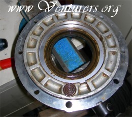
At this stage, we must measure the ring gear's thrust washer clearance. It's impossible to measure with "classical" metrological tools, the gear housing being closed. To help us, we use a nice American product called Plastigage. This is a fine plastic string, to put on the clearance area. The paper tape have a metric and an imperial scale printed on. My choice was for a 0.05 mm to 0.15 mm range ( = 0.002 to 0.006 inch).
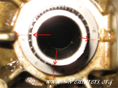
We cut 4 little pieces of Plastigage and place them on the thrust washer (diametricaly). The original thrust washer (1.8 mm) has been replace by a 1.4 mm thickness part (stage 43). We knew that we had increased the ring gear's shims until 0.8mm ( originally it was 0.5 mm ), I have compensated it directly with a thinner thrust washer. We can see with difficulty the Plastigage (red color).
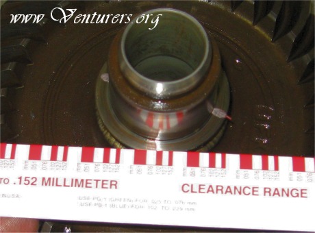
We re-close the assembly, with the correct tightening torques everywhere, (do not rotate the gears with Plastigage in place!) and we re-open it. We can see that the Plastigage parts has been crushed. We can read the clearance directly, with the help of the printed scale, as shown. The measurement is 0.076mm (= 0.003 inch), and it's too little, the recommended clearance is 0.1 to 0.2 mm ( = 0.004 to 0.0078 inch).
My final choice was for a 1.2mm thrust washer. Note that the part number's end show the part's thickness.
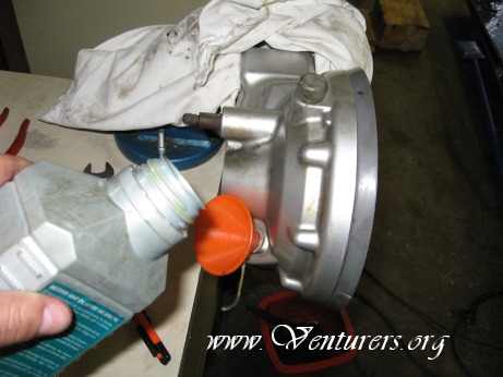
After carefuly close the assembly, we fill the oil (hypoid 80W90), before it's back to the swing arm. 0.2 liter for the quantity. The 4 connecting chromed nuts must be tighten to 30 ft/lb torque. Don't forget: grease well the shaft's splines, apply sealant on the connecting surfaces gear housing/swing arm.
Special thanks to Rick Haferkamp, and my wife for her patience !
Pief vum Elsass
Pierre-François Birgaentzlé
Venture # 2124
Back to page one
10/29/2007
Last update: 10:11 PM Sunday, November 4, 2007
|